
To download please look at the download center Sample Code Library ID: 101051
Sample Code Library | Rockwell Automation | US
Overview
The Condition Monitoring for Motion Axis V3 AOI (Add-On Instruction) is a software-based condition monitoring solution for Logix motion applications.
The AOI monitors a selected motion-axis signal during normal machine operation, records a baseline profile, and then compares the live signal against that stored profile during subsequent machine cycles.
When the monitored signal deviates from the stored profile beyond user-defined limits for a specified amount of time, the AOI can identify a disturbance condition.
This allows machine builders to use existing motion-system data to detect changes in machine operation without requiring additional sensors or specialized condition-monitoring hardware.
The AOI can be used with Virtual Torque Sensor (VTS) to monitor the motor's estimated air-gap torque and identify mechanical changes in the machine. Rockwell documentation specifically identifies applications including jam detection, belt tension verification, and mechanical issue detection.
How Does the AOI Work?
The Condition Monitoring AOI operates using two primary states:
1. Recording
During the recording state, the AOI monitors the selected input signal and creates a stored profile representing the machine's normal operating behavior.
For example, when VTS is used as the monitored signal, the AOI can record the torque profile produced by a healthy machine during a normal production cycle.
This profile becomes the baseline against which future machine cycles are compared.
In example below the blue line is the recorded signal and the green line represents the active motor signal

2. Monitoring
After a baseline has been established, the AOI enters the monitoring state.
During normal operation, the AOI continuously compares the actual input signal against the saved signal profile.
The difference between the live signal and the saved profile is referred to as the signal offset.
If the signal offset exceeds the configured minimum or maximum limits for longer than the configured disturbance time, the AOI sets the Sts_DisturbanceDetected status bit.
These signals are shown plotted below:
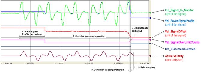
Condition Monitoring Logic
The basic detection process can be summarized as:
Normal machine cycle → Record baseline → Monitor live signal → Compare against baseline → Detect deviation → Generate disturbance
The AOI uses three important settings to determine when a disturbance has occurred:
- Set_MaxSignalOffset – Maximum allowable positive deviation from the stored profile.
- Set_MinSignalOffset – Maximum allowable negative deviation from the stored profile.
- Set_DisturbanceTimeLim_msec – How long the signal must remain outside the configured limits before a disturbance is detected.
Rockwell documentation describes the disturbance time limit in relation to the motion group's coarse update period. The AOI counts the number of updates for which the signal remains outside the configured limits before setting the disturbance status.
Example Using Virtual Torque Sensor
One of the most useful applications is combining the Condition Monitoring AOI with the Virtual Torque Sensor (VTS) feature.
For example, consider a rotary knife application.
During commissioning, the machine operates with a new, properly functioning blade. The VTS torque signal is recorded by the Condition Monitoring AOI and becomes the baseline torque profile.
During production, the AOI continuously compares the current torque profile against the recorded profile.
If the blade becomes worn or damaged, the amount of torque required during the cutting portion of the cycle can change.
The AOI detects the difference between the normal torque profile and the current torque profile and can generate a disturbance indication.
Rockwell training material demonstrates this concept using worn and broken blades, where changes in the torque profile result in signal-over-limit events.
Applications
Jam Detection
A machine jam can cause the torque required by a motor to change rapidly.
A simple torque threshold may not always be effective because a jam can occur at different points in the machine cycle. Comparing the live torque profile against a known-good profile allows the system to detect deviations from normal machine behavior.
Rockwell identifies jam detection as one of the primary applications for the Condition Monitoring AOI.
Belt Tension Monitoring
The AOI can also be used to assist with belt replacement and tensioning.
A torque profile can be recorded from a properly tensioned belt. After the belt is replaced, the new torque profile can be compared against the original profile.
Adjustments can then be made to the belt tension until the new profile sufficiently matches the baseline.
Mechanical Condition Monitoring
Changes in the machine's torque profile can provide an indication of developing mechanical problems.
Potential applications include detecting:
- Gearbox damage
- Bearing problems
- Coupling damage
- Ballscrew issues
- Mechanical wear
- Rotary knife blade wear
- Broken blades
- Other changes in mechanical loading
Gearbox tooth damage, bearing damage, coupling damage, ballscrew damage, and worn or broken blades as potential applications for this type of torque-profile monitoring.
Key Parameters
| Parameter | Description |
|---|---|
| Inp_Axis | Motion axis associated with the monitoring application |
| Inp_Signal_to_Monitor | Signal being monitored, such as Axis.TorqueEstimate |
| Inp_MachineCycleStart | Indicates the beginning of a machine cycle |
| Set_MachineCyclesToUpdateProfile | Determines how frequently the saved profile can be updated |
| Set_DisturbanceTimeLim_msec | Time the signal must remain outside the limits before detection |
| Set_MaxSignalOffset | Maximum allowable positive signal deviation |
| Set_MinSignalOffset | Maximum allowable negative signal deviation |
| Cfg_Recording_Enable | Enables the recording/baseline function |
| Sts_DisturbanceDetected | Indicates that a disturbance has been detected |
| Val_SavedSignalProfile | Stored baseline signal profile |
| Val_SignalOffset | Difference between the live signal and saved profile |
| Val_SignalOverLimitCounts | Number of signal updates exceeding the configured limits |
These parameters allow the AOI to be adapted to the specific characteristics of the machine and monitored signal.
Updating the Baseline
Machine conditions can naturally change over time due to factors such as normal mechanical wear or changes in loading.
The AOI can therefore be configured to update the stored signal profile after a specified number of machine cycles.
This allows the baseline to adapt to gradual changes in machine operation while still detecting abnormal disturbances.
Care should be taken when using automatic profile updating. If the machine is already operating under an abnormal condition, automatically updating the baseline could cause that abnormal condition to become part of the reference profile.
VTS + Condition Monitoring
The combination of Virtual Torque Sensor and the Condition Monitoring AOI is particularly useful for machine builders.
VTS provides the estimated motor air-gap torque, while the AOI provides the logic necessary to compare the current torque profile against a known-good machine profile.
Together, they can turn the servo system into a useful source of machine-condition information.
For example:
Kinetix Drive → VTS → Torque Profile → Condition Monitoring AOI → Detect Deviation → Machine Response
The response to a detected disturbance can then be determined by the machine application. Depending on the application, the controller could generate an alarm, stop production, request maintenance, or initiate another programmed response.
Click here to view our Knowledge Base Artical on VTS
Summary
The Condition Monitoring for Motion Axis V3 AOI provides a flexible method for monitoring the condition of mechanical systems using data already available from a Logix motion system.
By recording a known-good machine profile and comparing it against live operating data, the AOI can identify deviations that may indicate jams, mechanical wear, incorrect belt tension, damaged components, or other changes in machine behavior.
When combined with Kinetix Virtual Torque Sensor, the AOI provides a powerful method of monitoring mechanical condition without requiring a dedicated torque sensor.
Instead of simply monitoring whether the motor is moving, the system can monitor whether the machine is behaving the way it normally should.